4 أنواع من التشوهات المحلية في عملية ختم المعادن

الوقت المقدر للقراءة: 37 الدقائق
مقدمة عملية ختم المعدن
عملية الختم الأساسية مثل القطع ، والانحناء ، والسحب العميق ، بالإضافة إلى ذلك ستكون هناك عمليات تشكيل أخرى ، مثل عمليات المدرسة ، والتشفيه ، والانتفاخ ، وتقليل الختم. تشترك عملية الختم في التشوه المحلي ، فهي كلها من خلال طريقة التشوه المحلية لتغيير شكل المادة أو العملية وحجمها الفارغ. وهذا يعني أنه مع مجموعة متنوعة من الخصائص المختلفة للتشوه المحلي لتغيير الفراغ (أو عن طريق الطمس والانحناء والرسم وطرق أخرى للمنتجات شبه المصنعة) ، يُطلق على شكل وحجم عملية الختم تشكيل. أو بالإضافة إلى الانحناء والسحب العميق لإنتاج تشوه البلاستيك ، يمكن تسمية عمليات الختم الأخرى بالتشكيل ، والشكل الرئيسي ، والتشفيه ، والانكماش ، والانتفاخ ، والتشكيل المتموج ، إلخ.
طرق القولبة المختلفة لها خصائصها المختلفة. فيما يتعلق بالشكل ، نظرًا لأنه تشوه أثر محلي ، فلن ينتج بشكل عام ظاهرة التجعد أو التصدع ، والمشكلة الرئيسية هي الربيع. للتشفيه ، الانتفاخ ، غالبًا ما تظهر ظاهرة تلف الشد ، ويرجع ذلك أساسًا إلى أنها تشوه شد ، منطقة تشوه إجهاد الشد كبيرة جدًا. غالبًا ما يكون سبب الانكماش والشفاه الخارجية وعدم الاستقرار والتجاعيد هو التشوه المفرط للضغط الضاغط ، لأنهم يتعرضون للتشوه الانضغاطي. في صياغة عملية التشكيل وتصميم القالب ، يجب تحديد كل معلمة عملية بشكل معقول وفقًا لخصائص التشوه.
في هذا البحث ، يتم استخدام تصميم قوالب التشفيه لأجزاء الجلبة كما هو موضح في الشكل 1-1 كحامل لعرض أربع عمليات تشكيل شاملة ، مثل التحجيم ، والتشفيه ، والانكماش ، والانتفاخ.

أربعة أنواع من التشوهات الموضعية
تصحيح الشكل
يشمل تصحيح الشكل التسوية والتشكيل ، والتي تنتمي إلى عملية تشكيل الضمادة. يتم تنفيذه في الغالب بعد الطمس ، والانحناء ، والسحب العميق ، وعمليات الختم الأخرى ، بشكل أساسي من أجل تقليم الخشونة ، نصف قطر الحشو ، أو بعض أشكال وأحجام أجزاء الختم إلى المتطلبات المؤهلة.
تتميز عملية التشكيل السلس للمدرسة بالخصائص التالية.
- إن دقة القالب المستخدم للمعايرة عالية لأن دقة قطعة العمل بعد المعايرة أعلى.
- فقط في الموضع المحلي لإجراءات العمل لإنتاج تشوه بلاستيكي صغير لتحقيق الغرض من تحسين الشكل ودقة الأبعاد للأجزاء.
- نظرًا لأن المعايرة تنتمي إلى عملية الإنهاء وأن الربيع الخلفي هو المشكلة الرئيسية ، يجب تطبيق قوة المعايرة على أجزاء العملية عندما تصل المكبس إلى المركز الميت السفلي. أفضل المعدات المستخدمة هي المكبس الناعم أو المكبس الميكانيكي مع جهاز حماية من الحمل الزائد والصلابة الجيدة.
التسوية
عادة ما يتم تنفيذ التسوية بعد عملية الطمس. مثل الطمس بعد إنتاج ثني القبة ، خاصةً الجهاز غير الملحوظ للقطع المستمر للقالب الناتج عن إنتاج أكثر تفاوتًا. من أجل تسطيح المتطلبات الأعلى للأجزاء ، يجب تسويتها.
وفقًا لسمك اللوح ومتطلبات السطح ، يمكنك استخدام تسوية القالب السلس أو تسوية قالب الأسنان.
بالنسبة للنعومة الرقيقة ولا تسمح بوجود مسافة بادئة على سطح الأجزاء ، يجب عمومًا استخدام تسوية القالب السلس. القالب الأملس له تأثير ضئيل على تغيير حالة الضغط الداخلي للمادة ، ولا يزال هناك ارتداد كبير ، خاصة بالنسبة لأجزاء المواد عالية القوة. تأثير التسوية ضعيف. في الإنتاج الفعلي ، أحيانًا يتم تكديس أجزاء إجراءات العمل من الخلف إلى الخلف (الانحناء في الاتجاه المعاكس) إلى المستوى ، والذي يمكن أن يحصل على تأثير معين. من أجل جعل التسوية لا تتأثر بدقة التوجيه للكتلة المنزلقة للضغط ، فإن قالب التسوية كان من الأفضل أن يتبنى هيكل عائم. كما هو موضح في الشكل 1-2 ، فإن قالب التسوية يكون سلسًا. تطبيق القالب السلس للمعايرة ، بسبب الارتداد الأكبر ، خاصة بالنسبة لأجزاء المواد عالية القوة ، يكون تأثير التسوية ضعيفًا نسبيًا.

شكل 1-2 رسم تخطيطي لقالب التسوية العائم السلس
بالنسبة لمتطلبات التسطيح العالية ، تكون المادة عبارة عن أجزاء سميكة أو يكون حد القوة عبارة عن أجزاء مواد صلبة عالية ، وعادةً ما تعتمد تسوية تسوية الأسنان. هناك نوعان من أشكال الأسنان المميتة: أسنان ناعمة وخشنة. تتقاطع الأسنان العلوية والسفلية ، كما هو موضح في الشكل 1-3 ، حيث تظهر الأسنان الدقيقة في الشكل 1-3 (أ) ، وتظهر الأسنان الخشنة في الشكل 1-3 (ب) ، و يظهر حجم الأسنان في الشكل. بعد التسوية بقالب التسوية الناعم ، فإن سطح قطعة العمل به آثار أسنان دقيقة متبقية. قالب تسوية الأسنان الخشنة مناسب للسمك الأصغر للألمنيوم والبرونز والنحاس والأجزاء الأخرى. قالب تسوية الأسنان يجعل المستوى المدرسي للأجزاء يشكل العديد من النقاط الصغيرة من تشوه البلاستيك ، ويغير حالة الإجهاد الأصلية للأجزاء ، ويقلل من الارتداد ، ويكون تأثير التسوية جيدًا.
يمكن حساب قوة التسوية وفقًا للصيغة التالية:
F = AP (1-1)
في الصيغة:
قوة التسوية F ، N ؛
أ- مساحة أجزاء التسوية ، مم2;
P - الضغط لكل وحدة مساحة تسوية ، MPa ، كما هو موضح في الجدول 1-1.

الشكل 1-3 رسم تخطيطي لمحاذاة الأسنان
| أساليب | P (ميجا باسكال) | أساليب | P (ميجا باسكال) |
| تسوية سطح أملس التسوية | 50~80 | فتح تشكيل أجزاء الشكل | 50~100 |
| غرامة تسوية الأسنان التسوية | 80~120 | أجزاء الرسم العميق لتقليل الشرائح وفي الأسفل ، تشكيل الجانب | 150~200 |
| تسوية الأسنان الخشنة التسوية | 100~150 |
التشكيل
التشكيل الذي يشيع استخدامه في عمليات الرسم العميق أو الثني أو عمليات التشكيل الأخرى ، من خلال عملية التصنيع ، اتخذ الختم شكلًا أساسيًا ، ولكن ربما يكون نصف القطر كبيرًا جدًا ، أو لم يصل شكل وحجم معينين إلى متطلبات المنتجات ، يمكنك استخدام قالب بلاستيكي ينتج عملية تشوه بلاستيكية محلية ، لتحقيق الغرض من تحسين الدقة. يتشابه قالب التشكيل وقالب التشكيل قبل العملية ، لكن دقة جزء العمل وخشونته أعلى ، ونصف قطر الشريحة والفجوة أصغر.
طريقة تشكيل ثني الأجزاء موضحة في الشكل 1-4. عند التشكيل ، يكون إجراء العمل بأكمله في حالة إجهاد للضغط ثلاثي الاتجاهات ، مما يغير حالة الإجهاد لإجراءات العمل لتحقيق تأثير تشكيل أفضل. طول المنتج شبه النهائي قبل التشكيل أكبر قليلاً من طول الأجزاء لضمان أن المادة في حالة إجهاد ثلاثية عند التشكيل.

الشكل 1-4. تشكيل أجزاء الانحناء
يظهر شكل أجزاء الرسم ذات الحواف في الشكل 1-5. يتطلب تشكيل نصف قطر الحشوة عند جذر الحافة الصغيرة ملء الجزء الخارجي من الشرائح بمادة. إذا تغير نصف قطر الشرائح بشكل كبير ، يمكن أن يكون ارتفاع المنتجات شبه المصنعة أكبر من ارتفاع الأجزاء أثناء تصميم العملية. يمكن الحصول على ملحق المواد من جزء الجدار المستقيم أثناء التشكيل ، كما هو موضح في الشكل 1-5 (أ) (h 'ارتفاع المنتجات شبه النهائية ، و h ارتفاع المنتجات النهائية).
إذا كان ارتفاع المنتج شبه النهائي مساويًا لارتفاع الأجزاء ، فيمكن أيضًا الحصول على ملحق المواد عن طريق انكماش الحافة. ومع ذلك ، عندما يكون قطر الفلنجة كبيرًا جدًا ، لا يمكن تحقيق الانكماش في عملية التشكيل. في هذا الوقت ، لا يمكن استكمال المادة إلا بترقيق الجذر والمواد المجاورة ، كما هو موضح في الشكل 1-5 (ب) كما هو موضح ، من خصائص التشوه ، يعادل انتفاخًا صغيرًا في الشكل ، لذلك دقة التشكيل عالية ، لكن جزء التشوه من استطالة المادة يجب ألا يكون أكبر من 2% ~ 5% ، وإلا فقد ينكسر الاستطالة المفرطة للأجزاء.

يمكن لأجزاء السحب العميق الأسطوانية المستقيمة أن تجعل خلوص القالب البلاستيكي يساوي (0.9 ~ 0. 95) طنًا ، الأجزاء البلاستيكية الجدار المستقيم أرق قليلاً. يمكن أيضًا إجراء هذا التشكيل بالتزامن مع عملية السحب العميق النهائية.
التشفيه
التشفيه هو حافة الثقب أو الحافة الخارجية للجزء الواقع تحت تأثير القالب لإخراج الزاوية الرأسية أو زاوية معينة للحافة المستقيمة. وفقًا لخصائص العملية ، يمكن تقسيم التشفيه إلى حواف داخلية (كما هو موضح في الشكل 1-6 (أ) و (ب)) وتشفيه خارجي. يمكن تقسيم حافة الحافة الخارجية إلى حافة خارجية محدبة (كما هو موضح في الشكل 1-6 (ج)) ؛ الحافة الخارجية المقعرة مشفهة (كما هو موضح في الشكل 1-6 (د)). بالإضافة إلى ذلك ، وفقًا لتغيير سمك الحافة العمودية ، يمكن تقسيمها إلى تشفيه رقيق ثابت وتشفيه رقيق. أجزاء التشفيه الفعلية موضحة في الشكل 1-7.


تشفيه الثقب الداخلي
حفرة مستديرة التشفيه
- خصائص التشوه ومعامل التشفيه للفتحة المستديرة التشفيه
يمكن أيضًا استخدام طريقة الشبكة لتشفيه الثقوب المستديرة. يمكن تحليل التشوه بملاحظة التغيرات في الشبكة قبل وبعد التشوه ، كما هو مبين في الشكل 1-8. يمكن أن نرى من الشكل أن منطقة التشوه هي الجزء الحلقي بين القطر d و D1. بعد التشفيه ، تتغير شبكة الإحداثيات من شكل المروحة إلى المستطيل. يمكن ملاحظة أن المادة الموجودة في منطقة التشوه تتمدد على طول الاتجاه العرضي ، وكلما اقتربت من الفوهة ، زاد الاستطالة ، والتي تكون قريبة من حالة إجهاد الشد أحادي الاتجاه. السلالة العرضية هي أكبر السلالات الرئيسية الثلاثة. لا تتغير المسافة بين الدوائر متحدة المركز بشكل كبير ، لذلك يكون التشوه الشعاعي صغيرًا ويقل الحجم الشعاعي قليلاً.
يتم تخفيف سمك جدار الحافة العمودية ، خاصة عند الفتحة. تعكس حالات الإجهاد والانفعال الموضحة في الشكل خصائص التشوه هذه للتحليل أعلاه. يتمثل الخطر الرئيسي في تشفيه الثقب المستدير في أن حافة الفتحة متصدعة. تعتمد حالة التمزق على درجة التشوه.

يتم تمثيل درجة تشوه التشفيه للفتحة الدائرية بنسبة القطر d للفتحة سابقة الصب قبل التشفيه إلى القطر D بعد التشفيه K. وهذا هو:
ك = د / د (1-2)
K يسمى معامل التشفيه. من الواضح أن K دائمًا أقل من 1. كلما كانت قيمة K أصغر ، زادت درجة التشوه. عند التشفيه ، يُطلق على الحد الأدنى للقيمة K التي يمكن الوصول إليها بشرط عدم تكسير حافة الثقب اسم معامل الحد من التشفيه الذي يعبر عنه Kmin. العوامل الرئيسية التي تؤثر على معامل التشفيه المحدد هي الخواص الميكانيكية للمادة ، وشكل الثقب ، ونسبة الفتحة قبل التشفيه إلى سمك المادة ، وطريقة معالجة ثقب المواد مسبقة الصنع ، وما إلى ذلك. تتم معالجتها بشكل رئيسي عن طريق التثقيب أو الحفر. يتم عرض معاملات التشفيه المحددة للفولاذ منخفض الكربون في ظل ظروف مختلفة ومعاملات التشفيه للمواد المختلفة في الجدول 1-2.
| شكل لكمة | طريقة معالجة الثقب | القطر النسبي للفتحة سابقة الصب | ||||||||||
| 100 | 50 | 35 | 20 | 15 | 10 | 8 | 6.5 | 5 | 3 | 1 | ||
| لكمة أسطوانية | الثقب | 0.80 | 0.70 | 0.60 | 0.50 | 0.45 | 0.42 | 0.40 | 0.37 | 0.35 | 0.30 | 0.25 |
| 0.85 | 0.75 | 0.65 | 0.60 | 0.55 | 0.52 | 0.50 | 0.50 | 0.48 | 0.47 | - | ||
| انتفاخ لكمة | الثقب | 0.70 | 0.60 | 0.52 | 0.45 | 0.40 | 0.36 | 0.33 | 0.31 | 0.30 | 0.25 | 0.20 |
| 0.75 | 0.65 | 0.57 | 0.52 | 0.48 | 0.45 | 0.44 | 0.43 | 0.42 | 0.42 | - |
ملحوظة:
عندما يكون ملف K.دقيقة عند استخدام القيمة في الجدول ، ستظهر شقوق صغيرة على حافة الفم بعد التشفيه الفعلي. إذا لم يتم السماح لقطعة العمل بالتصدع ، فيجب زيادة معامل التشفيه بمقدار 10% ~ 15%.
يمكن معرفة الارتفاع h لأول رسم عميق ثم تحول الثقب من الشكل 1-10 (محسوبًا وفقًا للخط الأوسط).
- عملية حساب تشفيه الثقب المستدير
في حساب عملية التشفيه ، من الضروري حساب قطر الفتحة الجاهزة d وفقًا لحجم القطعة D وحساب ارتفاع التشفيه H. عندما لا يمكن قلب الفراغ المسطح مباشرة عند الارتفاع المطلوب H ، فإنه من الضروري رسم الثقوب الأولى في الجزء السفلي من الرسم ، ثم شفة. تناقش هذه الورقة نوعين من الحواف المسطحة وتشفيه السحب العميق على التوالي.
قبل التشفيه ، يجب معالجة الثقوب المسبقة الصنع على القضبان ، كما هو موضح في الشكل 1-9. صيغة تحديد قطر الحفرة الجاهزة د هي كما يلي

د = D-2 (H-0.43r-0.72t) (1-3)
يمكن تحويل المعادلة أعلاه لحساب الارتفاع H للحافة الرأسية.
H = (D - d) / 2 + 0.43r + 0.72 t = D (1-K) / 2 + 0.43 r + 0.72t (1-4)
إذا تم استبدال K في المعادلة أعلاه ، يمكن الحصول على الحد الأقصى لارتفاع التشفيه المسموح به Hmax.
حالأعلى = D (1-Kدقيقة) + 0.43 ص + 0.72 طن (1-5)
عندما يكون ارتفاع الشغل H > H.الأعلى، قد يؤدي تشكيل ثقب تحول إلى كسر حافة الاتجاه للأجزاء. يمكن استخدام الرسم العميق الأول في هذا الوقت ، ومن ثم يمكن تثقيب وتشويه الجزء السفلي من الرسم. في هذه الحالة ، يجب تحديد الحد الأقصى للارتفاع الذي يمكن الوصول إليه عن طريق التشفيه بعد السحب المسبق أولاً ، ومن ثم يجب تحديد ارتفاع قطر الرسم والتثقيب المسبق وفقًا لارتفاع التشفيه وارتفاع الأجزاء.

ع = (دد) / 2 - (ص + ر / 2) - π (ص + ر / 2) / 2
بعد الانتهاء
h≈ (Dd) / 2 + 0.57r = D (1 - k) / 2 + 0.57r (1-6)
قطر الحفرة الجاهزة د هو
d = KD أو d = D + 1. 14 r - 2 h (1-7)
ارتفاع الرسم h هو
ح '= ح - ح + ص (1-8)
تشفيه ، ظاهرة ترقق الفم العمودية الحافة أكثر خطورة. يتم حساب قيمتها التقريبية على النحو التالي.
")
- حساب قوة التشفيه
قوة التشفيه F صغيرة بشكل عام. عند استخدام المثقاب الأسطواني السفلي المسطح ، يمكن حساب قوة التشفيه للفتحة المستديرة على النحو التالي
F = 1.1 π (Dd) t σس (1-10)
في الصيغة:
F- قوة دوران الثقب ، N ؛
D - القطر المتوسط للحافة العمودية بعد التشفيه ، مم ؛
د - القطر الأولي للفتحة الدائرية ، مم ؛
ر سماكة الفراغ ، مم ؛
σس —نقطة إنتاج المادة ، MPa.
- قلب تصميم القالب
بشكل عام ، هناك الكثير من أوجه التشابه بين تحول القالب ورسم القالب ، وهناك أيضًا حاملات فارغة وليست حوامل فارغة ، رسمية وقلب. في الوقت نفسه ، لا يحتاج قالب التقليب عمومًا إلى ضبط إطار القالب. يوضح الشكل 1-11 أبعاد وأشكال العديد من الثقوب المستديرة الشائعة. الشكل 1-11 (أ) ~ (ج) يوضح لكمة التشفيه ذات الثقوب الكبيرة. فيما يتعلق بفائدة تشوه التشفيه ، فإن لكمة القطع المكافئ هي الأفضل ، واللكمة الكروية هي التالية ، واللكمة المسطحة هي الثانية. من صعوبة معالجة لكمة لرؤية العكس.
يوضح الشكل 1-11 (د) ~ (و) نهاية مثقبة بجزء توجيه أطول. الشكل 1-11 (د) يستخدم للتشفيه بقطر ثقب يزيد عن 10 مم ، الشكل 1-11 (هـ) يستخدم للتشفيه بقطر ثقب أقل من 10 مم ، والشكل 1-11 (و ) يستخدم للتشفيه غير الدقيق بدون ثقب مسبق. يجب أن يكون نصف قطر شريحة التثقيب أكبر ما يمكن ، مما يساعد على دوران الثقب.
الفجوة السطحية الفردية بين القالب المحدب والمُقعر أكثر سمكًا (0. 75 ~ 0.85) مرة.

شكل 1-11 هيكل التشفيه والتشكيل وأبعاد الثقوب المستديرة

شكل 1-11 هيكل التشفيه والتشكيل وأبعاد الثقوب المستديرة
تشفيه ثقب غير دائري
تسمى الفتحة المستديرة أيضًا بالفتحة ذات الشكل الخاص ، بواسطة نصف قطر انحناء مختلف للقوس المحدب ، والقوس المقعر ، والخطوط المستقيمة ، وتتشكل بسبب اختلاف خصائص الإجهاد والتشوه ، ويمكن اعتبار منطقة الجزء الخطي الثاني على أنها يمكن اعتبار تشوه الانحناء ، منطقة قسم القوس المحدب I تشوه التشفيه ، على أنه يمكن اعتبار منطقة الجزء الثالث من القوس المقعر على أنها رسم تشوه ، كما هو موضح في الشكل 1-12.

يتم حساب شكل وحجم التمدد للثقوب الجاهزة وفقًا لطريقة التمدد الخاصة بالثني والدوران والرسم على التوالي ويتم توصيلها بقوس دائري أملس. معامل التشفيه كF للثقب غير الدائري (يشير عمومًا إلى معامل التشفيه لجزء القوس الدائري الصغير) يمكن أن يكون أقل من معامل التشفيه K للفتحة الدائرية ، وهو تقريبًا
كF= (0.85 ~ 0.90) ك (1-11)
بالنسبة لمعامل التشفيه الحدي للفتحات غير الدائرية ، يرجى الرجوع إلى الجدول 1-3 وفقًا للزاوية المركزية α لكل مقطع قوس.
| α (°) | 180~360 | 165 | 150 | 135 | 120 | 105 | 90 | 75 | 60 | 45 | 30 | 15 | 0 | |
| نسبة d / t | 50 | 0.8 | 0.73 | 0.67 | 0.6 | 0.53 | 0.47 | 0.4 | 0.33 | 0.21 | 0.2 | 0.14 | 0.07 | الانحناء تشوه |
| 33 | 0.6 | 0.55 | 0.5 | 0.45 | 0.4 | 0.35 | 0.3 | 0.25 | 0.2 | 0.15 | 0.1 | 0.05 | ||
| 20 | 0.52 | 0.48 | 0.43 | 0.39 | 0.35 | 0.30 | 0.26 | 0.22 | 0.17 | 0.13 | 0.09 | 0.04 | ||
| 12~8.3 | 0.5 | 0.46 | 0.42 | 0.38 | 0.33 | 0.29 | 0.25 | 0.21 | 0.17 | 0.13 | 0.08 | 0.04 | ||
| 6.6 | 0.48 | 0.44 | 0.4 | 0.36 | 0.32 | 0.28 | 0.24 | 0.2 | 0.16 | 0.12 | 0.08 | 0.04 | ||
| 5 | 0.46 | 0.42 | 0.38 | 0.35 | 0.31 | 0.27 | 0.23 | 0.19 | 0.15 | 0.12 | 0.08 | 0.04 | ||
| 3.3 | 0.45 | 0.41 | 0.375 | 0.34 | 0.30 | 0.26 | 0.225 | 0.185 | 0.145 | 0.11 | 0.08 | 0.04 |
تشفيه الحافة الخارجية
وفقًا لخصائص التشوه ، يمكن تقسيم الحافة الخارجية إلى حواف استطالة وتشفيه انضغاطي.
نوع الاستطالة التشفيه
تشفيه على مستوى أو سطح على طول منحنى مقعر وغير مغلق تقع جميعها في هذه الفئة ، كما هو موضح في الشكل 1-13. السمة الشائعة للتشفيه هي أن منطقة التشوه للكتل تنتج بشكل أساسي تشوه استطالة عرضي تحت تأثير إجهاد الشد العرضي ، لذلك من السهل كسر الحافة ، وغالبًا ما يتم التعبير عن درجة التشوه بواسطة Eامتداد.
هامتداد= ب / (ر ب) (1-12)
تظهر التشوهات المسموح بها للمواد الشائعة في الجدول 1-4.
| الاسم والعلامة التجارية للمادة | Εمعدل× 100 | Εالضغط× 100 | الاسم والعلامة التجارية للمادة | Εمعدل× 100 | Εالضغط× 100 | ||||||
| صب المطاط | تشكيل القالب | صب المطاط | تشكيل القالب | صب المطاط | تشكيل القالب | صب المطاط | تشكيل القالب | ||||
| نحاس | H62 سوفت | 30 | 40 | 8 | 45 | صلب | 10 | - | 38 | - | 10 |
| H62 hard | 10 | 14 | 4 | 16 | 20 | - | 22 | - | 10 | ||
| H68 soft | 35 | 45 | 8 | 55 | 1Cr18Ni9 soft | - | 15 | - | 10 | ||
| H68 half hard | 10 | 14 | 4 | 16 | 1Cr18Ni9 hard | - | 40 | - | 10 | ||
| 2Cr18Ni9 | - | 40 | - | 01 | |||||||
| سبائك الألومنيوم | L4 soft | 25 | 30 | 6 | 40 | سبائك الألومنيوم | LF2 hard | 5 | 8 | 3 | 12 |
| L4 hard | 5 | 8 | 3 | 12 | LY12 soft | 14 | 20 | 6 | 30 | ||
| LF21 soft | 23 | 30 | 6 | 40 | LY12 hard | 6 | 8 | 0.5 | 9 | ||
| LF21 hard | 5 | 8 | 3 | 12 | LY11 soft | 14 | 20 | 4 | 30 | ||
| LF2 soft | 20 | 25 | 6 | 35 | LY11 hard | 5 | 6 | 0 | 0 |
The elongated plane flanging deformation is similar to hole flanging. When flanging, the stress distribution in the deformation area is not uniform, which leads to the phenomenon that the height of the vertical edge is high at both ends and low in the middle after flanging. To obtain a flat flanging height, the contour lines at both ends of the billet should be trimmed before flanging. The shape shown by the dotted line in Fig. 1-13 (a) is shaped after trimming.
In the elongated surface flanging, the wrinkling phenomenon is easy to occur in the middle of the bottom of the billet, generally in the design of the die should be used to prevent the use of the strong pressing device, at the same time to create conditions conducive to flanging, to prevent the middle part of premature flanging caused by excessive elongation deformation and even cracking of the vertical edge.

Fig. 1-13. Elongation type flanging
Compression type flanging
The flanging of a plane or surface along a convex, unclosed curve is a compression flanging, as shown in Fig. 1-14. Its characteristic is that the billet deformation area is mainly subjected to tangential compressive stress, so the workpiece is easy to wrinkle when forming. Deformation degree Eالضغط is denoted as
هالضغط=b/(R+b) (1-13)

Fig. 1-14 Compression class flanging
Compression plane flanging deformation is similar to deep drawing, because of the uneven distribution of stress on the vertical edge during flanging, the height of the vertical edge of the part after flanging appears high in the middle and low at both ends.
To obtain a flat vertical edge, the expanded shape of the billet shall be modified, as shown in Fig. 1-14 (a) dashed line. Flanging can not be corrected when the height is small. In addition, when the flanging height is large, the mold should be designed to prevent wrinkling of the pressing device.
The structure of flanging die
The structure types of common flanging dies are shown in Fig. 1-15, which are similar to the structure of deep drawing dies

Fig. 1-15 Structure types of flanging dies
1—Push board; 2, 7, 9—Convex and concave die; 3—Die; 4—Punch;
5—Punching punch; 6—Blank holder ring; 8—Blanking concave die; 10—Roof
Fig. 1-16 shows the inner and outer flanging composite die. It can be seen from the workpiece parts drawing that the inner and outer edges of the workpiece need flanging. The blank is positioned on piece 7, and piece 7 is mounted on press plate 5. Part 7 itself is the flanging die of the inner edge. The pressing plate shall be assembled with the flanging die 3 of the outer edge to ensure its accurate position according to the clearance with H7/ h6. At this time, the pressing plate not only plays the role of pressing and shaping. So when pressing to the bottom dead center, it should be in rigid contact with the lower die seat, and finally plays the role of the top part.
After the inner edge flanging, under the action of the spring, the jacking block 6 jacked the workpiece from the inner edge flanging die 7. Push plate 8 because of the role of the spring, stamping always keep contact with the blank. To the bottom dead center point, and punch fixed plate 2 rigid contact, so push plate 8 also plays a shaping role, out of the workpiece is relatively smooth. On the mold out of the parts, taking into account the spring may be insufficient strength, the final use of rigid pushing device will be pushed out of the workpiece.

1—Outer flange punch; 2—Punch fixing plate; 3—Outer edge flanging die;4—Inner edge flanging punch; 5—Press plate; 6—Top piece block; 7—Inner edge flanging die; 8—Pushing plate
Bulging
Under the action of the die, the blank is forced to reduce the thickness and the surface area of the increase, to obtain the geometry of the parts of the stamping processing method is called bulging. The bulging process has its unique characteristics, the bulging deformation zone in the direction of the plate surface is a two-way tensile stress state, in the direction of the plate thickness is thinning deformation, that is, thickness thinning and surface area increased. Bulging is mainly used for the local forming of flat blank such as reinforcing bars, pattern patterns, and marks, the bulging of hollow blank such as bellows, high-pressure gas cylinders, and spherical containers, and the tensile forming of thin plates such as aircraft and automobile skin. The commonly used bulging methods include rigid die bulging and soft die bulging with liquid, gas, rubber, and other force media.
Due to the workpiece’s simple mold structure and uniform deformation, the soft die bulging can form the workpiece of complex shape. The research and application of soft die bulging have been paid more and more attention, such as hydraulic bulging, rubber bulging, explosive bulging, etc., as shown in figure 1-17, stainless steel pot produced by the bulging method.

Deformation characteristics of bulging
Fig. 1-18 shows the bulging deformation zone and its principal stress and strain diagram when the ball head punch bulges the blank. The blackened part represents the bulging area. The bulging deformation has the following characteristics.

- The bulging deformation due to the blank by the larger blank holder force, or because the blank diameter is more than 3 ~ 4 times the diameter of the die hole, the plastic deformation is limited to a fixed deformation range, the sheet material does not transfer to the deformation zone, nor from outside the deformation zone into the deformation zone.
- In the bulging deformation area, the bulging deformation is a bidirectional tensile stress state in the plate direction (the stress in the plate thickness direction is ignored). The deformation is mainly completed by thinning the material thickness direction supporting the elongation in the plate direction. After deformation, the material thickness decreases, and the surface area increases.
- Because the thickness of the blank relative to the external size of the blank is very small, the change of the tensile stress along the thickness direction of the plate during the bulging deformation is very small, so when the bulging force is removed after the rebound is small, the geometry of the workpiece is easy to be fixed, and the dimensional accuracy is easy to ensure.
- Due to the bidirectional tensile stress state of the material in the direction of the plate during bulging deformation, the forming limit is mainly restricted by tensile fracture. So the deformation is not easy to produce the phenomenon of instability and wrinkle, the surface of the finished parts is smooth and the quality is good.
Flat billet undulation forming
When the size of the blank is larger than 3 times the deformation size, the deformation only occurs in the contact area with the punch, which is the local bulging of the blank. The common ones in production are the pressing reinforcement, convex hulls, pits, patterns, and marks, etc. Figure 1-19 shows some examples of undulation forming using this method. After undulating forming stamping parts, because of the change of the moment of inertia of the parts and the material work hardening, can effectively improve the stiffness and strength of the parts. The technology of pressing reinforcing bars is widely used in production.

Fig. 1-19 Examples of bulging parts
The forms and dimensions of the stiffeners are shown in Table 1-5. When in the billet edge local bulging, because the edge material to shrink, so should be set aside in advance cutting margin, after forming and then excised.
| اسم | Diagram | ص | ح | D or B | ص | |
| Pressed rib | 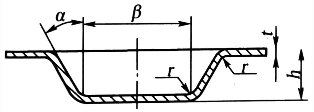 | (3-4)t | (2-3)t | (7-10)t | (1-2)t | |
| Embossing | 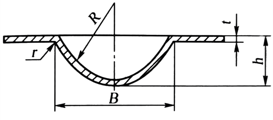 | (1.5-2)t | ≥3h | (0.5-1.5)t | 15°~30° | |
| Diagram | D(mm) | L(mm) | l(mm) | |||
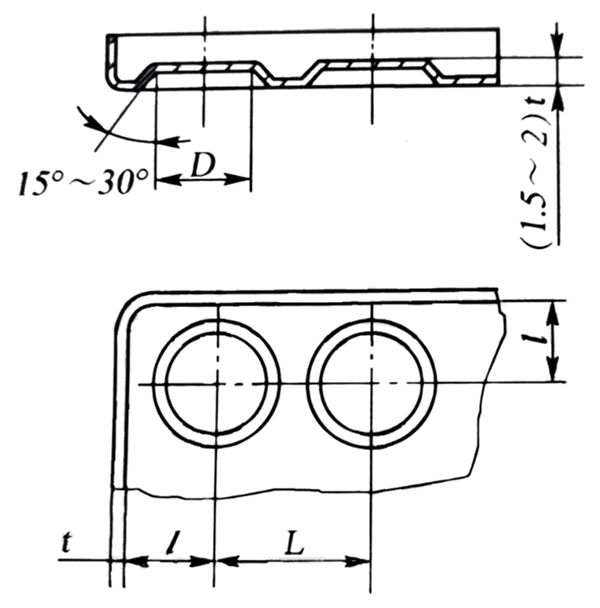 | 6.5 8.5 10.5 13 15 18 24 31 36 43 48 55 | 10 13 15 18 22 26 34 44 51 60 68 78 | 6 7.5 9 11 13 16 20 26 30 35 40 45 |
There are usually two methods to determine the degree of ultimate deformation in the undulating forming method, namely, the test method and the calculation method. The ultimate deformation degree of undulating forming is mainly affected by material properties, the geometrical shape of parts, die structure, bulging method, and lubrication. Especially for the parts of complex shape, the distribution of stress and strain is more complex. The dangerous parts and the degree of ultimate deformation are generally determined by the method of test. For relatively simple undulating forming parts, the ultimate deformation degree can be approximately determined according to the following equation, as shown in Fig. 1-20.
εultimate ل0 ( l – l0 ) x 100% ≤ K [ δ ] (1-14)
In the formula,
εultimate —The ultimate deformation degree of undulating forming;
l、l0— Are respectively the length before and after deformation of the material, mm;
[ δ ]—Elongation of the section of material;
K—Shape coefficient, reinforcement K = 0. 70 ~ 0.75 (spherical reinforcement is the largest value, trapezoidal reinforcement is the smallest value).

If the required stiffeners of the part exceed the limit deformation degree, the method as shown in Fig. 1-21 can be adopted. In the first procedure, a large diameter spherical punch is used to bulge to obtain a process part as shown in Fig. 1-21 (a). In the second procedure, the required shape and size of the part are obtained as shown in Fig. 1-21 (b). If these two processes do not meet the requirements, it is necessary to reduce the depth of the workpiece.

- When the rigid punch is used to press the stiffeners in the flat billet, the following formula can calculate the required punching pressure.
F=tσبKL (1-15)
In the formula,
F—Impulse pressure, N;
L—Girth of stiffeners, mm;
t—Material thickness, mm;
σب—The tensile strength of the material, MPa;
K—Coefficient, generally take 0.7~1.0 (take a large value when the shape of the reinforcement is narrow and deep, take a small value when the width is shallow).
- If local bulging of small parts with a thickness of less than 1.5mm and a forming area of less than 2000 mm2 is carried out on the crank press, the required punching pressure F can be approximated by the following formula.
F=Kt2A (1-16)
In the formula,
F—Bulging punch pressure, N;
T—Material thickness, mm;
A—Bulging area, mm2;
K—Coefficient is 200~300 N/mm4 for steel and 50 ~ 200 N/mm4 for copper and aluminum.
The bulge of the hollow billet
The bulging of a hollow billet is commonly known as bulging. It is a stamping process in which the hollow working parts or tubular blank expands outward along the radial direction. By this method, products or parts such as high-pressure gas cylinders, spherical containers, bellows, bicycle tee joints, and so on can be formed.
Degree of bulging deformation
When the hollow billet bulges, the material is subjected to the action of tensile stress to produce tensile deformation, and the ultimate deformation degree is expressed by the bulging coefficient K, as shown in Fig. 1-22.
K = dالأعلى/D (1-17)
In the formula,
K—Bulging coefficient and the limit bulging coefficient (dالأعلى reaches the limit value d’الأعلى when bulging) is expressed by Kالأعلى;
دالأعلى—The maximum diameter of the parts after bulging, mm;
D—Original diameter of hollow billet, mm.

The relation between the limit bulging coefficient K and the tangential elongation of the billet is
δ = ( dالأعلى – D ) = K – 1 or K = 1 – δ (1-18)
Since the deformation degree of the billet is limited by the elongation of the material, the corresponding limit bulging coefficient can be calculated according to the above formula. The approximate value of the limit bulging coefficient of the material can be determined by looking up the table. Table 1-6 and Table 1-7 are the bulging coefficients of some materials for reference.
| مادة | Relative thickness of blank (t / D) x (%) | Relative thickness of blank (t / D) x (%) | Relative thickness of blank (t / D) x (%) | Relative thickness of blank (t / D) x (%) |
| 0.35~0.45 | 0.28~0.32 | |||
| Annealing | Without annealing | Annealing | Without annealing | |
| الألومنيوم | 1.25 | 1.2 | 1.2 | 1.15 |
| 10 steel | 1.2 | 1.10 | 1.15 | 1.05 |
| Bulging method | Limit bulging coefficient |
| Using a simple bulge of rubber | 1.2~1.25 |
| Bulging of a blank by applying an eraser under axial pressure | 1.6~1.7 |
| Bulging when heated locally to 200~500℃ | 2.0~2.1 |
| The end of the tapered punch is bulged by heating to 380℃ | ~3.0 |
Calculation of bulging billet
As can be seen from Fig. 1-22, blank diameter D is
د = دالأعلى/ K (1-19)
The length of blank L is
L =l [ l + (0.3~0.4) δ ] + b (1-20)
In the formula,
l—The length of the bus in the deformation zone, mm;
δ—The elongation of billet in tangential stretching;
B—Margin of trimming, generally take b=5~15 mm.
0.3-0.4—The coefficient required to reduce the height due to tangential elongation.
Determination of bulging force
The bulging force F required for hollow billet bulging can be calculated as follows:
F = p*A (1-21)
In the formula,
p—Pressure per unit area required for bulging, MPa;
A—Bulging area, mm2.
The pressure p per unit area required for bulging can be approximated by the equation below.
p = 1.16 σب* 2t / dالأعلى (1-22)
In the formula,
σب—Tensile strength of the material, Mpa;
دالأعلى—The maximum bulging diameter, mm;
t—The original thickness of the material, mm.
Bulging method
Hollow parts bulging methods are generally divided into rigid punch bulging and soft punch bulging.
As shown in Fig. 1-23, the rigid punch is bulging. The punch is in the form of a component flap, and the tapered pellet is used to push the split punch out to make the working parts bulge out of the required shape. The more the number of lobed punches, the shape of the workpiece, and the accuracy is better. But the disadvantages are that it is difficult to get the correct rotating body with high precision, the deformation is not uniform, and the die structure is complex.

1—Split punch; 2—Spindle; 3—Blank; 4—Plunger
As shown in Fig. 1-24, soft punch bulging, the principle of which is the use of rubber, liquid, gas, and steel shot instead of rigid punch. Soft punch bulging billet deformation uniform can form complex shapes of parts, so it is widely used in production.

Fig. 1-24 Bulging of soft punch
1—Punch; 2—Block concave die; 3—Rubber; 4—Side wedge; 5—Liquid
Shrink mouth
Shrinkage is a forming process in which the diameter of the mouth of a tubular or pre-drawn cylindrical part is reduced by pressure at the opening, which is divided into punch compression mouth and rotary compression mouth. Shrink technology is widely used in daily life, can be used for bullet cases, shells, steel gas cylinders, bicycle frame riser, bicycle cushion saddle pipe, steel pipe drawing, and so on.
Deformation degree and deformation characteristics of shrinkage mouth
Fig. 1-25 shows the stress-strain diagram of the shrinkage. In the process of cutting, the maximum principal stress should be the tangential compression stress, the billet deformation zone by the effect of the bidirectional compression stress, so that the billet height increased, wall thickness and diameter decreased. At the same time, in the non-deformed zone, axial instability deformation may occur on the cylinder wall under the action of shrinkage pressure F. Therefore, the ultimate deformation degree of shrinkage is mainly restricted by the instability condition, and the main problem to be solved is to prevent the instability.
The shrinkage coefficient N is used to represent the degree of deformation of the shrinkage, as shown in Fig. 1-25.
n = d / D (1-23)

In the formula,
d—Diameter after shrinking, mm;
D—Diameter before shrinkage, mm.
The smaller the shrinkage coefficient N, the greater the degree of deformation. Table 1-8 is the average shrinkage coefficient of different materials and thicknesses, and Table 1-9 is the reference value of the allowable limit shrinkage coefficient of different materials and supporting modes. It can be seen from Table 1-8 and Table 1-9 that the better the plasticity of the material, the larger the thickness, and the smaller the shrinkage coefficient. In addition, when the die supports the cylinder wall, the limiting shrinkage coefficient can be smaller.
| مادة | Material thickness t (mm) | Material thickness t (mm) | Material thickness t (mm) |
| 1 | >0.5 ~ 1 | ~ 0.5 | |
| صلب | 0.7 ~ 0.65 | 0.75 | 0.8 |
| نحاس | 0.7 ~ 0.65 | 0.8 ~ 0.7 | 0.85 |
| مادة | Supporting way | Supporting way | Supporting way |
| Unsupported | Outside support | The internal and external support | |
| الألومنيوم | 0.65 ~ 0.72 | 0.53 ~ 0.57 | 0.27 ~ 0.32 |
| Duralumina (annealed) | 0.73 ~ 0.80 | 0.60 ~ 0.63 | 0.35 ~ 0.40 |
| Duralumina (quenching) | 0.75 ~ 0.80 | 0.68 ~ 0.72 | 0.40 ~ 0.43 |
| Brass H62, H68 | 0.65 ~ 0.70 | 0.50 ~ 0.55 | 0.27 ~ 0.32 |
| الفولاذ الطري | 0.70 ~ 0.75 | 0.55 ~ 0.60 | 0.30 ~ 0.35 |
Calculation of shrinkage process
The number of shrinkages
If the shrinkage coefficient n of the workpiece is greater than the allowable shrinkage coefficient, it can be a shrinkage forming. Otherwise, multiple contractions are required. The number of shrinkage k can be estimated according to the following formula.
k = lgn / lgn0 = ( lgd – lgD ) / lgn0 (1-24)
In the formula, n0 is the average shrinkage coefficient, as shown in Table 1-8.
In the case of multiple contractions, the first contraction coefficient n1 = 0.9 n0 is generally taken, and the subsequent one is nx = (1.05~1.10) n0. It is best to carry out one annealing treatment after each contraction procedure.
Diameter of each shrinkage
د1=n1د
د2=nxد1=n1نxد
د3=nxد1=n1نx2د
…
دx=nxدx-1=n1نxx-1د (1-25)
دx shall be equal to the shrinkage diameter of the workpiece. After the shrinkage, due to the rebound, the workpiece should be 0.5% ~ 0.8% larger than the mold size.
Height of billet
For the shrinking workpiece as shown in Fig. 1-26, the height of the billet before shrinking is calculated by the following formula.

Workpieces as shown in Figure 1-26 (a) :

Workpieces as shown in Figure 1-26 (b) :

Workpieces as shown in Figure 1-26 (c) :

Reducing force
As shown in Fig. 1-26 (a), the shrinkage force of the tapered part can be calculated by the formula below.

In the formula,
μ—The friction coefficient between the blank and the contact surface of the die;
b—Tensile strength of the material, MPa;
K—Velocity coefficient, K=1.15 when working on the crank press.
The other symbols are shown in Figure 1-26.
Shrinking die structure
As shown in Fig. 1-27, the structure of a typical shrinkage die is made of No.08 steel with a material thickness of 1mm. The workpiece is formed by the deep drawing of the cylinder and then the shrinkage process. The working principle of the die is that the blank is first put into the outer support sleeve, the upper die is downward, the outer support sleeve and the concave die are first contacted to complete the shrinkage forming. The mold pushes the material through the way of punching.

1—Pushrod; 2—Lower template; 3、14—Bolts; 4、11—Pin; 5—Fixed plate; 6—Block; 7—Swing sleeve; 8—Die; 9—Top outlet; 10—Template; 12—Feeding rod; 13—Mold handle; 15—Guide pillar; 16—Guide bush


Make it easier for me to design more complex forming die.