4 Typy lokálních deformací v procesu lisování kovů

Předpokládaná doba čtení: 37 minut
Metal Stamping Process introduction
The most basic stamping process such as cutting, bending, deep drawing, in addition to this there will be other forming processes, such as school, flanging, bulging, and reducing stamping processes. The stamping process has in common is belong to local deformation, they are all through the local deformation method to change the shape of the material or process and blank size. That is to say, with a variety of different properties of local deformation to change the blank (or by blanking, bending, drawing, and other methods of semi-finished products) shape and size of the stamping process is called forming. Or in addition to bending and deep drawing to produce plastic deformation, other stamping processes can be called forming, the main shape, flanging, shrinkage, bulging and undulating forming, etc.
Different molding methods have their own different characteristics. Regarding the shape, because it is a local trace deformation, generally will not produce wrinkling or cracking phenomenon, the main problem is springback. For flanging, bulging, often appear the phenomenon of tensile damage, this is mainly because they are tensile deformation, deformation area tensile stress is too large. About shrinkage and outer flanging, instability and wrinkling are often caused by excessive deformation compressive stress, because they are subjected to compression deformation. In the formulation of forming process and die design, each process parameter should be reasonably determined according to the deformation characteristics.
In this paper, the flanging dies design of bushing parts as shown in Fig. 1-1 is used as the carrier to comprehensively display four forming processes, such as sizing, flanging, shrinking, and bulging.

Four types of local deformations
Shape correction
Shape correction includes leveling and shaping, which belongs to the dressing forming process. It is mostly carried out after blanking, bending, deep drawing, and other stamping processes, mainly in order to trim the roughness, fillet radius, or some shape and size of the stamping parts to the qualified requirements.
The school smooth shaping process has the following characteristics.
- The precision of the mold used for calibration is high because the precision of the workpiece after calibration is higher.
- Only in the local position of the working procedure to produce small plastic deformation to achieve the purpose of improving the shape and dimensional accuracy of parts.
- Because the calibration belongs to the finishing process and the springback is the main problem, the calibration force should be applied to the process parts when the press reaches the bottom dead center. The best equipment used is the fine press or the mechanical press with good stiffness and overload protection device.
The leveling
Leveling is usually carried out after the blanking process. As the blanking after the production of the dome bend, especially the non-pressing device of the continuous die blanking resulting from the production of more uneven. For the flatness of the higher requirements of the parts will need to be leveled.
According to the thickness of the sheet and the requirements of the surface, you can use smooth die leveling or tooth die leveling.
For thin soft and do not allow indentation on the surface of the parts, generally should be used smooth die leveling. The smooth die has little effect on changing the internal stress state of the material, and there is still a large rebound, especially for the parts of high strength materials. The leveling effect is poor. In actual production, sometimes the working procedure parts are stacked back to back (bending in the opposite direction) to level, which can receive a certain effect. In order to make the leveling not affected by the guiding accuracy of the sliding block of the press, the leveling die had better adopt a floating structure. As shown in Fig. 1-2, the leveling die is smooth. Application of smooth die for calibration, due to the larger rebound, especially for high strength material parts, the leveling effect is relatively poor.

Fig. 1-2 Schematic diagram of smooth floating leveling die
For the flatness requirements are high, the material is thick parts or the strength limit is high hard material parts, usually, adopt tooth leveling die leveling. There are two types of tooth shape die: fine teeth and coarse teeth. The upper teeth and the lower teeth are intersected, as shown in Fig. 1-3, in which fine teeth are shown in Fig. 1-3 (a), coarse teeth are shown in Fig. 1-3 (b), and tooth size is shown in the figure. After leveling with a fine-tooth leveling die, the surface of the workpiece has residual fine-tooth marks. Coarse tooth leveling die is suitable for the smaller thickness of aluminum, bronze, brass and other parts. Tooth leveling die makes the school plane of the parts form many small dots of plastic deformation, change the original stress state of the parts, reduce the rebound, and the leveling effect is good.
Leveling force can be calculated according to the following formula:
F=AP (1-1)
In the formula:
F—leveling force, N;
A—area of leveling parts, mm2;
P—Pressure per unit area of leveling, MPa, as shown in Table 1-1.

Fig. 1-3 Tooth alignment die schematic diagram
| Methods | P (MPa) | Methods | P (MPa) |
| Smooth surface leveling die leveling | 50~80 | Open shape parts shaping | 50~100 |
| Fine tooth leveling die leveling | 80~120 | Deep drawing parts to reduce the fillet and on the bottom, side shaping | 150~200 |
| Coarse tooth leveling die leveling | 100~150 |
The shaping
Shaping commonly used in deep drawing, bending, or other forming processes, through the process of machining, stamping has basically taken shape, but maybe radius is too large, or a certain shape and size have not yet reached the requirements of products, you can use plastic mold produce localized plastic deformation process, to achieve the purpose of improving precision. The shaping mold and the forming mold before the process are similar, but the working part’s precision and roughness are higher, and the radius of the fillet and the gap are smaller.
The shaping method of bending parts is shown in Fig. 1-4. When shaping, the whole working procedure is in the stress state of three-direction compression, which changes the stress state of the working procedure to achieve a better shaping effect. The length of the semi-finished product before shaping is slightly larger than the length of the parts to ensure that the material is in a three-way stress state when shaping.

Fig. 1-4. Shaping of bending parts
The shaping of flanged drawing parts is shown in Fig. 1-5. The shaping of the fillet radius at the root of the small flange requires that the outer part of the fillet is filled with material. If the radius of fillet changes greatly, the height of semi-finished products can be larger than the height of parts during process design. The material supplement can be obtained from the straight wall part during shaping, as shown in Fig. 1-5 (a) (h’ is the height of semi-finished products, and h is the height of finished products).
If the height of the semi-finished product is equal to the height of the parts, the material supplement can also be obtained by the contraction of the flange. However, when the diameter of the flange is too large, the shrinkage cannot be achieved in the process of shaping. At this time, the material can only be supplemented by the thinning of the root and the nearby material, as shown in Fig. 1-5 (b) as shown, from the deformation characteristics, is equivalent to a small deformation bulging, so the shaping accuracy is high, but the deformation part of the material elongation should not be greater than 2% ~ 5%, otherwise, excessive elongation of the parts may break.

Straight cylindrical deep drawing parts can make plastic mold clearance is equal to (0.9~0. 95) t, plastic parts straight wall slightly thinner. This shaping can also be done in conjunction with the final deep drawing process.
Obrubování
Flanging is the hole edge or the outer edge of the part under the action of the mold to turn out the vertical or a certain Angle of the straight edge. According to its process characteristics, flanging can be divided into inner flanging (as shown in Fig. 1-6 (a) and (b)) and outer flanging. Outer edge flanging can be divided into convex outer edge flanging (as shown in Fig. 1-6 (c)); The concave outer edge flanged (as shown in Fig. 1-6 (d)). In addition, according to the change of vertical edge thickness, it can be divided into constant thin flanging and thinning flanging. The actual flanging parts are shown in Fig. 1-7.


Flanging the inner hole
Round hole flanging
- Deformation characteristics and flanging coefficient of round hole flanging
The grid method can also be used for flanging round holes. Deformation can be analyzed by observing the changes of the mesh before and after deformation, as shown in Fig. 1-8. It can be seen from the Figure that the deformation area is the annular part between diameter d and D1. After flanging, the coordinate grid changes from the fan shape to the rectangle. It can be seen that the material in the deformation zone elongates along the tangential direction, and the closer it is to the orifice, the greater the elongation will be, which is close to the state of unidirectional tensile stress. The tangential strain is the largest of the three principal strains. The distance between the concentric circles does not change significantly, so the radial deformation is small and the radial size is slightly reduced.
The wall thickness of the vertical edge is thinned, especially at the orifice. The states of stress and strain showed in the figure reflect these deformation characteristics of the above analysis. The main danger of round hole flanging is that the edge of the hole is cracked. The condition of rupture depends on the degree of deformation.

The degree of flanging deformation of the circular hole is represented by the ratio of diameter d of the precast hole before flanging to diameter D after flanging K. That is:
K=d/D (1-2)
K is called the flanging coefficient. Obviously, K is always less than 1. The smaller the value of K, the greater the degree of deformation. When flanging, the minimum value K that can be reached under the condition that the hole edge does not crack is called the limit flanging coefficient expressed by Kmin. The main factors that affect the limit flanging coefficient are the material’s mechanical properties, the shape of the punch, the ratio of the aperture before flanging to the thickness of the material, and the processing method of the material prefabricated hole, etc. Prefabricated holes are mainly processed by punching or drilling. The limiting flanging coefficients of low carbon steel under various conditions and the flanging coefficients of various materials are shown in Table 1-2.
| Punch form | Hole processing method | Precast hole relative diameter | ||||||||||
| 100 | 50 | 35 | 20 | 15 | 10 | 8 | 6.5 | 5 | 3 | 1 | ||
| Cylindrical punch | Hole punching | 0.80 | 0.70 | 0.60 | 0.50 | 0.45 | 0.42 | 0.40 | 0.37 | 0.35 | 0.30 | 0.25 |
| 0.85 | 0.75 | 0.65 | 0.60 | 0.55 | 0.52 | 0.50 | 0.50 | 0.48 | 0.47 | — | ||
| Punch bulging | Hole punching | 0.70 | 0.60 | 0.52 | 0.45 | 0.40 | 0.36 | 0.33 | 0.31 | 0.30 | 0.25 | 0.20 |
| 0.75 | 0.65 | 0.57 | 0.52 | 0.48 | 0.45 | 0.44 | 0.43 | 0.42 | 0.42 | — |
Poznámka:
When the Kmin value in the table is used, small cracks will appear at the edge of the mouth after actual flanging. If the workpiece is not allowed to crack, the flanging coefficient should be increased by 10% ~ 15%.
The height h of the first deep drawing and then hole turning can be known from Fig. 1-10 (calculated according to the middle line).
- The process calculation of round hole flanging
In the flanging process calculation, it is necessary to calculate the diameter of the prefabricated hole d according to the size of the piece D and calculate the flanging height H. When the flat blank can not be directly turned out at the required height H, it is necessary to draw the first, punch holes at the bottom of the drawing, and then flange. This paper discusses two kinds of flat flanging and deep drawing flanging respectively.
Before flanging, prefabricated holes need to be processed on the billet, as shown in Fig. 1-9. The formula for determining the diameter of the prefabricated hole d is as follows

d = D-2 (H-0.43r-0.72t) (1-3)
The above equation can be converted to the calculation of the height H of the vertical edge.
H = (D – d) / 2 + 0.43r + 0.72 t = D(1-K)/2 + 0.43 r + 0.72t (1-4)
If K is substituted into the above equation, the maximum permissible flanging height Hmax can be obtained.
Hmax = D(1-Kmin) + 0.43 r + 0.72t (1-5)
When the height of the workpiece is H>Hmax, a hole turning forming may lead to the fracture of the orientation edge of the parts. The first deep drawing can be used at this time, and then the bottom of the drawing can be punched and flanged. In this case, the maximum height that can be reached by flanging after pre-drawing should be determined first, and then the height of drawing and pre-punching diameter should be determined according to the height of flanging and the height of parts.

h=(D-d)/2 – (r + t/2) – π(r + t/2)/2
After finishing
h≈(D-d)/2 + 0.57r = D(1 – k)/2 + 0.57r (1-6)
The diameter of the precast hole d is
d = KD or d = D + 1. 14 r – 2 h (1-7)
The drawing height h is
h’=H – h + r (1-8)
Flanging, vertical edge mouth thinning phenomenon is more serious. Its approximate value is calculated as follows.
")
- Calculation of flanging force
Flanging force F is generally small. When the cylindrical flat bottom punch is used, the flanging force of the round hole can be calculated as
F = 1.1 π (D-d) t σs (1-10)
In the formula:
F—hole turning force, N;
D—the median diameter of the vertical edge after flanging, mm;
d—the initial diameter of the circular hole, mm;
t—thickness of blank, mm;
σs —the yield point of the material, MPa.
- Turn over die design
In general, turning die and drawing die have a lot of similarities, there are also blank holders and not blank holders, formal and flip. At the same time, the turn-over die generally does not need to set the die frame. Fig. 1-11 shows the dimensions and shapes of several common round hole turn-over punches. Fig. 1-11 (a)~(c) shows the flanging punch with large holes. In terms of the benefit of flanging deformation, the parabolic punch is the best, the ball punch is the next, and the flat punch is the second. From the punch processing difficulty to see the opposite.
Fig. 1-11 (d) ~(f) shows a punch end with a longer guide part. Fig. 1-11 (d) is used for flanging with a hole diameter of more than 10mm, Fig. 1-11 (e) is used for flanging with a hole diameter of less than 10mm, and Fig. 1-11 (f) is used for inexact flanging without a pre-hole. The radius of the fillet of the punch should be as large as possible, which is conducive to hole turning.
The single surface gap between the convex and concave die is (0. 75 ~ 0.85) times thicker.

Fig. 1-11 Flanging punch and die structure and dimensions for round holes

Fig. 1-11 Flanging punch and die structure and dimensions for round holes
Non-circular hole flanging
The round hole is also called the special-shaped hole, by different curvature radius of the convex arc, concave arc, and straight lines, forming due to each part of the stress and deformation properties are different, linear part II area can be considered as bending deformation, convex arc section area I flanging deformation, can be regarded as concave arc part III area can be seen as drawing deformation, as shown in Fig. 1-12.

The shape and expansion size of the prefabricated holes are calculated according to the expansion method of bending, turning, and drawing respectively and connected by a smooth circular arc. The flanging coefficient KF of the non-circular hole (generally refers to the flanging coefficient of the small circular arc part) can be less than the flanging coefficient K of the circular hole, which is roughly
KF= (0.85 ~ 0.90)K (1-11)
For the limit flanging coefficient of non-circular holes, please refer to Table 1-3 according to the central angle α of each arc segment.
| α(°) | 180~360 | 165 | 150 | 135 | 120 | 105 | 90 | 75 | 60 | 45 | 30 | 15 | 0 | |
| The ratio of d/t | 50 | 0.8 | 0.73 | 0.67 | 0.6 | 0.53 | 0.47 | 0.4 | 0.33 | 0.21 | 0.2 | 0.14 | 0.07 | Ohýbání deformace |
| 33 | 0.6 | 0.55 | 0.5 | 0.45 | 0.4 | 0.35 | 0.3 | 0.25 | 0.2 | 0.15 | 0.1 | 0.05 | ||
| 20 | 0.52 | 0.48 | 0.43 | 0.39 | 0.35 | 0.30 | 0.26 | 0.22 | 0.17 | 0.13 | 0.09 | 0.04 | ||
| 12~8.3 | 0.5 | 0.46 | 0.42 | 0.38 | 0.33 | 0.29 | 0.25 | 0.21 | 0.17 | 0.13 | 0.08 | 0.04 | ||
| 6.6 | 0.48 | 0.44 | 0.4 | 0.36 | 0.32 | 0.28 | 0.24 | 0.2 | 0.16 | 0.12 | 0.08 | 0.04 | ||
| 5 | 0.46 | 0.42 | 0.38 | 0.35 | 0.31 | 0.27 | 0.23 | 0.19 | 0.15 | 0.12 | 0.08 | 0.04 | ||
| 3.3 | 0.45 | 0.41 | 0.375 | 0.34 | 0.30 | 0.26 | 0.225 | 0.185 | 0.145 | 0.11 | 0.08 | 0.04 |
Flanging the outer edge
According to the deformation properties, the outer flanging can be divided into elongation flanging and compression flanging.
Elongation type flanging
Flanging on a plane or surface along a concave and unclosed curve all falls into this category, as shown in Fig. 1-13. The common feature of flanging is that the deformation zone of the billet mainly produces tangential elongation deformation under the action of tangential tensile stress, so the edge is easy to crack, and the degree of deformation is often expressed by Eextension.
Eextension=b/(R-b) (1-12)
The allowable deformations of common materials are shown in Table 1-4.
| Name and brand of material | Εratex100 | Εtlakx100 | Name and brand of material | Εratex100 | Εtlakx100 | ||||||
| Rubber molding | Mold forming | Rubber molding | Mold forming | Rubber molding | Mold forming | Rubber molding | Mold forming | ||||
| brass | H62 soft | 30 | 40 | 8 | 45 | steel | 10 | — | 38 | — | 10 |
| H62 hard | 10 | 14 | 4 | 16 | 20 | — | 22 | — | 10 | ||
| H68 soft | 35 | 45 | 8 | 55 | 1Cr18Ni9 soft | — | 15 | — | 10 | ||
| H68 half hard | 10 | 14 | 4 | 16 | 1Cr18Ni9 hard | — | 40 | — | 10 | ||
| 2Cr18Ni9 | — | 40 | — | 01 | |||||||
| Slitina hliníku | L4 soft | 25 | 30 | 6 | 40 | Slitina hliníku | LF2 hard | 5 | 8 | 3 | 12 |
| L4 hard | 5 | 8 | 3 | 12 | LY12 soft | 14 | 20 | 6 | 30 | ||
| LF21 soft | 23 | 30 | 6 | 40 | LY12 hard | 6 | 8 | 0.5 | 9 | ||
| LF21 hard | 5 | 8 | 3 | 12 | LY11 soft | 14 | 20 | 4 | 30 | ||
| LF2 soft | 20 | 25 | 6 | 35 | LY11 hard | 5 | 6 | 0 | 0 |
The elongated plane flanging deformation is similar to hole flanging. When flanging, the stress distribution in the deformation area is not uniform, which leads to the phenomenon that the height of the vertical edge is high at both ends and low in the middle after flanging. To obtain a flat flanging height, the contour lines at both ends of the billet should be trimmed before flanging. The shape shown by the dotted line in Fig. 1-13 (a) is shaped after trimming.
In the elongated surface flanging, the wrinkling phenomenon is easy to occur in the middle of the bottom of the billet, generally in the design of the die should be used to prevent the use of the strong pressing device, at the same time to create conditions conducive to flanging, to prevent the middle part of premature flanging caused by excessive elongation deformation and even cracking of the vertical edge.

Fig. 1-13. Elongation type flanging
Compression type flanging
The flanging of a plane or surface along a convex, unclosed curve is a compression flanging, as shown in Fig. 1-14. Its characteristic is that the billet deformation area is mainly subjected to tangential compressive stress, so the workpiece is easy to wrinkle when forming. Deformation degree Etlak is denoted as
Etlak=b/(R+b) (1-13)

Fig. 1-14 Compression class flanging
Compression plane flanging deformation is similar to deep drawing, because of the uneven distribution of stress on the vertical edge during flanging, the height of the vertical edge of the part after flanging appears high in the middle and low at both ends.
To obtain a flat vertical edge, the expanded shape of the billet shall be modified, as shown in Fig. 1-14 (a) dashed line. Flanging can not be corrected when the height is small. In addition, when the flanging height is large, the mold should be designed to prevent wrinkling of the pressing device.
The structure of flanging die
The structure types of common flanging dies are shown in Fig. 1-15, which are similar to the structure of deep drawing dies

Fig. 1-15 Structure types of flanging dies
1—Push board; 2, 7, 9—Convex and concave die; 3—Die; 4—Punch;
5—Punching punch; 6—Blank holder ring; 8—Blanking concave die; 10—Roof
Fig. 1-16 shows the inner and outer flanging composite die. It can be seen from the workpiece parts drawing that the inner and outer edges of the workpiece need flanging. The blank is positioned on piece 7, and piece 7 is mounted on press plate 5. Part 7 itself is the flanging die of the inner edge. The pressing plate shall be assembled with the flanging die 3 of the outer edge to ensure its accurate position according to the clearance with H7/ h6. At this time, the pressing plate not only plays the role of pressing and shaping. So when pressing to the bottom dead center, it should be in rigid contact with the lower die seat, and finally plays the role of the top part.
After the inner edge flanging, under the action of the spring, the jacking block 6 jacked the workpiece from the inner edge flanging die 7. Push plate 8 because of the role of the spring, stamping always keep contact with the blank. To the bottom dead center point, and punch fixed plate 2 rigid contact, so push plate 8 also plays a shaping role, out of the workpiece is relatively smooth. On the mold out of the parts, taking into account the spring may be insufficient strength, the final use of rigid pushing device will be pushed out of the workpiece.

1—Outer flange punch; 2—Punch fixing plate; 3—Outer edge flanging die;4—Inner edge flanging punch; 5—Press plate; 6—Top piece block; 7—Inner edge flanging die; 8—Pushing plate
Bulging
Under the action of the die, the blank is forced to reduce the thickness and the surface area of the increase, to obtain the geometry of the parts of the stamping processing method is called bulging. The bulging process has its unique characteristics, the bulging deformation zone in the direction of the plate surface is a two-way tensile stress state, in the direction of the plate thickness is thinning deformation, that is, thickness thinning and surface area increased. Bulging is mainly used for the local forming of flat blank such as reinforcing bars, pattern patterns, and marks, the bulging of hollow blank such as bellows, high-pressure gas cylinders, and spherical containers, and the tensile forming of thin plates such as aircraft and automobile skin. The commonly used bulging methods include rigid die bulging and soft die bulging with liquid, gas, rubber, and other force media.
Due to the workpiece’s simple mold structure and uniform deformation, the soft die bulging can form the workpiece of complex shape. The research and application of soft die bulging have been paid more and more attention, such as hydraulic bulging, rubber bulging, explosive bulging, etc., as shown in figure 1-17, stainless steel pot produced by the bulging method.

Deformation characteristics of bulging
Fig. 1-18 shows the bulging deformation zone and its principal stress and strain diagram when the ball head punch bulges the blank. The blackened part represents the bulging area. The bulging deformation has the following characteristics.

- The bulging deformation due to the blank by the larger blank holder force, or because the blank diameter is more than 3 ~ 4 times the diameter of the die hole, the plastic deformation is limited to a fixed deformation range, the sheet material does not transfer to the deformation zone, nor from outside the deformation zone into the deformation zone.
- In the bulging deformation area, the bulging deformation is a bidirectional tensile stress state in the plate direction (the stress in the plate thickness direction is ignored). The deformation is mainly completed by thinning the material thickness direction supporting the elongation in the plate direction. After deformation, the material thickness decreases, and the surface area increases.
- Because the thickness of the blank relative to the external size of the blank is very small, the change of the tensile stress along the thickness direction of the plate during the bulging deformation is very small, so when the bulging force is removed after the rebound is small, the geometry of the workpiece is easy to be fixed, and the dimensional accuracy is easy to ensure.
- Due to the bidirectional tensile stress state of the material in the direction of the plate during bulging deformation, the forming limit is mainly restricted by tensile fracture. So the deformation is not easy to produce the phenomenon of instability and wrinkle, the surface of the finished parts is smooth and the quality is good.
Flat billet undulation forming
When the size of the blank is larger than 3 times the deformation size, the deformation only occurs in the contact area with the punch, which is the local bulging of the blank. The common ones in production are the pressing reinforcement, convex hulls, pits, patterns, and marks, etc. Figure 1-19 shows some examples of undulation forming using this method. After undulating forming stamping parts, because of the change of the moment of inertia of the parts and the material work hardening, can effectively improve the stiffness and strength of the parts. The technology of pressing reinforcing bars is widely used in production.

Fig. 1-19 Examples of bulging parts
The forms and dimensions of the stiffeners are shown in Table 1-5. When in the billet edge local bulging, because the edge material to shrink, so should be set aside in advance cutting margin, after forming and then excised.
| název | Diagram | R | h | D or B | r | |
| Pressed rib | 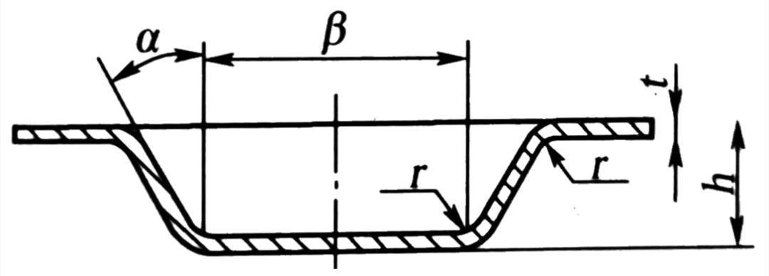 | (3-4)t | (2-3)t | (7-10)t | (1-2)t | |
| Embossing | 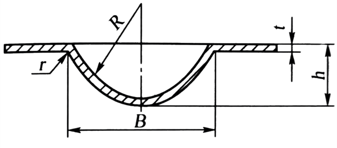 | (1.5-2)t | ≥3h | (0.5-1.5)t | 15°~30° | |
| Diagram | D(mm) | L(mm) | l(mm) | |||
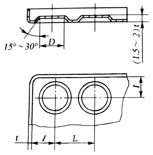 | 6.5 8.5 10.5 13 15 18 24 31 36 43 48 55 | 10 13 15 18 22 26 34 44 51 60 68 78 | 6 7.5 9 11 13 16 20 26 30 35 40 45 |
There are usually two methods to determine the degree of ultimate deformation in the undulating forming method, namely, the test method and the calculation method. The ultimate deformation degree of undulating forming is mainly affected by material properties, the geometrical shape of parts, die structure, bulging method, and lubrication. Especially for the parts of complex shape, the distribution of stress and strain is more complex. The dangerous parts and the degree of ultimate deformation are generally determined by the method of test. For relatively simple undulating forming parts, the ultimate deformation degree can be approximately determined according to the following equation, as shown in Fig. 1-20.
εultimate l0 ( l – l0 ) x 100% ≤ K [ δ ] (1-14)
In the formula,
εultimate —The ultimate deformation degree of undulating forming;
l、l0— Are respectively the length before and after deformation of the material, mm;
[ δ ]—Elongation of the section of material;
K—Shape coefficient, reinforcement K = 0. 70 ~ 0.75 (spherical reinforcement is the largest value, trapezoidal reinforcement is the smallest value).

If the required stiffeners of the part exceed the limit deformation degree, the method as shown in Fig. 1-21 can be adopted. In the first procedure, a large diameter spherical punch is used to bulge to obtain a process part as shown in Fig. 1-21 (a). In the second procedure, the required shape and size of the part are obtained as shown in Fig. 1-21 (b). If these two processes do not meet the requirements, it is necessary to reduce the depth of the workpiece.

- When the rigid punch is used to press the stiffeners in the flat billet, the following formula can calculate the required punching pressure.
F=tσbKL (1-15)
In the formula,
F—Impulse pressure, N;
L—Girth of stiffeners, mm;
t—Material thickness, mm;
σb—The tensile strength of the material, MPa;
K—Coefficient, generally take 0.7~1.0 (take a large value when the shape of the reinforcement is narrow and deep, take a small value when the width is shallow).
- If local bulging of small parts with a thickness of less than 1.5mm and a forming area of less than 2000 mm2 is carried out on the crank press, the required punching pressure F can be approximated by the following formula.
F=Kt2A (1-16)
In the formula,
F—Bulging punch pressure, N;
T—Material thickness, mm;
A—Bulging area, mm2;
K—Coefficient is 200~300 N/mm4 for steel and 50 ~ 200 N/mm4 for copper and aluminum.
The bulge of the hollow billet
The bulging of a hollow billet is commonly known as bulging. It is a stamping process in which the hollow working parts or tubular blank expands outward along the radial direction. By this method, products or parts such as high-pressure gas cylinders, spherical containers, bellows, bicycle tee joints, and so on can be formed.
Degree of bulging deformation
When the hollow billet bulges, the material is subjected to the action of tensile stress to produce tensile deformation, and the ultimate deformation degree is expressed by the bulging coefficient K, as shown in Fig. 1-22.
K = dmax/D (1-17)
In the formula,
K—Bulging coefficient and the limit bulging coefficient (dmax reaches the limit value d’max when bulging) is expressed by Kmax;
dmax—The maximum diameter of the parts after bulging, mm;
D—Original diameter of hollow billet, mm.

The relation between the limit bulging coefficient K and the tangential elongation of the billet is
δ = ( dmax – D ) = K – 1 or K = 1 – δ (1-18)
Since the deformation degree of the billet is limited by the elongation of the material, the corresponding limit bulging coefficient can be calculated according to the above formula. The approximate value of the limit bulging coefficient of the material can be determined by looking up the table. Table 1-6 and Table 1-7 are the bulging coefficients of some materials for reference.
| Materiál | Relative thickness of blank (t / D) x (%) | Relative thickness of blank (t / D) x (%) | Relative thickness of blank (t / D) x (%) | Relative thickness of blank (t / D) x (%) |
| 0.35~0.45 | 0.28~0.32 | |||
| Annealing | Without annealing | Annealing | Without annealing | |
| Hliník | 1.25 | 1.2 | 1.2 | 1.15 |
| 10 steel | 1.2 | 1.10 | 1.15 | 1.05 |
| Bulging method | Limit bulging coefficient |
| Using a simple bulge of rubber | 1.2~1.25 |
| Bulging of a blank by applying an eraser under axial pressure | 1.6~1.7 |
| Bulging when heated locally to 200~500℃ | 2.0~2.1 |
| The end of the tapered punch is bulged by heating to 380℃ | ~3.0 |
Calculation of bulging billet
As can be seen from Fig. 1-22, blank diameter D is
D = dmax/ K (1-19)
The length of blank L is
L =l [ l + (0.3~0.4) δ ] + b (1-20)
In the formula,
l—The length of the bus in the deformation zone, mm;
δ—The elongation of billet in tangential stretching;
B—Margin of trimming, generally take b=5~15 mm.
0.3-0.4—The coefficient required to reduce the height due to tangential elongation.
Determination of bulging force
The bulging force F required for hollow billet bulging can be calculated as follows:
F = p*A (1-21)
In the formula,
p—Pressure per unit area required for bulging, MPa;
A—Bulging area, mm2.
The pressure p per unit area required for bulging can be approximated by the equation below.
p = 1.16 σb* 2t / dmax (1-22)
In the formula,
σb—Tensile strength of the material, Mpa;
dmax—The maximum bulging diameter, mm;
t—The original thickness of the material, mm.
Bulging method
Hollow parts bulging methods are generally divided into rigid punch bulging and soft punch bulging.
As shown in Fig. 1-23, the rigid punch is bulging. The punch is in the form of a component flap, and the tapered pellet is used to push the split punch out to make the working parts bulge out of the required shape. The more the number of lobed punches, the shape of the workpiece, and the accuracy is better. But the disadvantages are that it is difficult to get the correct rotating body with high precision, the deformation is not uniform, and the die structure is complex.

1—Split punch; 2—Spindle; 3—Blank; 4—Plunger
As shown in Fig. 1-24, soft punch bulging, the principle of which is the use of rubber, liquid, gas, and steel shot instead of rigid punch. Soft punch bulging billet deformation uniform can form complex shapes of parts, so it is widely used in production.

Fig. 1-24 Bulging of soft punch
1—Punch; 2—Block concave die; 3—Rubber; 4—Side wedge; 5—Liquid
Shrink mouth
Shrinkage is a forming process in which the diameter of the mouth of a tubular or pre-drawn cylindrical part is reduced by pressure at the opening, which is divided into punch compression mouth and rotary compression mouth. Shrink technology is widely used in daily life, can be used for bullet cases, shells, steel gas cylinders, bicycle frame riser, bicycle cushion saddle pipe, steel pipe drawing, and so on.
Deformation degree and deformation characteristics of shrinkage mouth
Fig. 1-25 shows the stress-strain diagram of the shrinkage. In the process of cutting, the maximum principal stress should be the tangential compression stress, the billet deformation zone by the effect of the bidirectional compression stress, so that the billet height increased, wall thickness and diameter decreased. At the same time, in the non-deformed zone, axial instability deformation may occur on the cylinder wall under the action of shrinkage pressure F. Therefore, the ultimate deformation degree of shrinkage is mainly restricted by the instability condition, and the main problem to be solved is to prevent the instability.
The shrinkage coefficient N is used to represent the degree of deformation of the shrinkage, as shown in Fig. 1-25.
n = d / D (1-23)

In the formula,
d—Diameter after shrinking, mm;
D—Diameter before shrinkage, mm.
The smaller the shrinkage coefficient N, the greater the degree of deformation. Table 1-8 is the average shrinkage coefficient of different materials and thicknesses, and Table 1-9 is the reference value of the allowable limit shrinkage coefficient of different materials and supporting modes. It can be seen from Table 1-8 and Table 1-9 that the better the plasticity of the material, the larger the thickness, and the smaller the shrinkage coefficient. In addition, when the die supports the cylinder wall, the limiting shrinkage coefficient can be smaller.
| Materiál | Material thickness t (mm) | Material thickness t (mm) | Material thickness t (mm) |
| 1 | >0.5 ~ 1 | ~ 0.5 | |
| Ocel | 0.7 ~ 0.65 | 0.75 | 0.8 |
| Mosaz | 0.7 ~ 0.65 | 0.8 ~ 0.7 | 0.85 |
| Materiál | Supporting way | Supporting way | Supporting way |
| Unsupported | Outside support | The internal and external support | |
| Hliník | 0.65 ~ 0.72 | 0.53 ~ 0.57 | 0.27 ~ 0.32 |
| Duralumina (annealed) | 0.73 ~ 0.80 | 0.60 ~ 0.63 | 0.35 ~ 0.40 |
| Duralumina (quenching) | 0.75 ~ 0.80 | 0.68 ~ 0.72 | 0.40 ~ 0.43 |
| Brass H62, H68 | 0.65 ~ 0.70 | 0.50 ~ 0.55 | 0.27 ~ 0.32 |
| Měkká ocel | 0.70 ~ 0.75 | 0.55 ~ 0.60 | 0.30 ~ 0.35 |
Calculation of shrinkage process
The number of shrinkages
If the shrinkage coefficient n of the workpiece is greater than the allowable shrinkage coefficient, it can be a shrinkage forming. Otherwise, multiple contractions are required. The number of shrinkage k can be estimated according to the following formula.
k = lgn / lgn0 = ( lgd – lgD ) / lgn0 (1-24)
In the formula, n0 is the average shrinkage coefficient, as shown in Table 1-8.
In the case of multiple contractions, the first contraction coefficient n1 = 0.9 n0 is generally taken, and the subsequent one is nX = (1.05~1.10) n0. It is best to carry out one annealing treatment after each contraction procedure.
Diameter of each shrinkage
d1=n1D
d2=nXd1=n1nXD
d3=nXd1=n1nX2D
…
dX=nXdx-1=n1nXx-1D (1-25)
dX shall be equal to the shrinkage diameter of the workpiece. After the shrinkage, due to the rebound, the workpiece should be 0.5% ~ 0.8% larger than the mold size.
Height of billet
For the shrinking workpiece as shown in Fig. 1-26, the height of the billet before shrinking is calculated by the following formula.

Workpieces as shown in Figure 1-26 (a) :

Workpieces as shown in Figure 1-26 (b) :

Workpieces as shown in Figure 1-26 (c) :

Reducing force
As shown in Fig. 1-26 (a), the shrinkage force of the tapered part can be calculated by the formula below.

In the formula,
μ—The friction coefficient between the blank and the contact surface of the die;
b—Tensile strength of the material, MPa;
K—Velocity coefficient, K=1.15 when working on the crank press.
The other symbols are shown in Figure 1-26.
Shrinking die structure
As shown in Fig. 1-27, the structure of a typical shrinkage die is made of No.08 steel with a material thickness of 1mm. The workpiece is formed by the deep drawing of the cylinder and then the shrinkage process. The working principle of the die is that the blank is first put into the outer support sleeve, the upper die is downward, the outer support sleeve and the concave die are first contacted to complete the shrinkage forming. The mold pushes the material through the way of punching.

1—Pushrod; 2—Lower template; 3、14—Bolts; 4、11—Pin; 5—Fixed plate; 6—Block; 7—Swing sleeve; 8—Die; 9—Top outlet; 10—Template; 12—Feeding rod; 13—Mold handle; 15—Guide pillar; 16—Guide bush


Make it easier for me to design more complex forming die.