3 choses que vous devez savoir sur le pliage de pièces par poinçonnage
Temps de lecture estimé : 14 minutes
Calculation of unfolded dimensions of bent parts by coup de poing
Determination of the position of the curved neutral layer
The bent neutral layer refers to a metal layer whose length remains unchanged before and after bending deformation, so the expanded length of the bent neutral layer is the blank size of the bent part. In order to calculate the expanded size of the curved neutral layer, the position of the neutral layer must first be determined. The position of the neutral layer can be determined by its bending radius ρ, as shown in Figure 1-1. ρ can be calculated according to the following formula empirically.
ρ=r+xt
Where ρ— the bending radius of the neutral layer, mm;
r —Inner bending radius, mm;
l—material thickness, mm;
x—Displacement coefficient of neutral layer,
Please see the following table for more information:

| r/ t | 0.1 | 0.2 | 0.3 | 0.4 | 0.5 | 0.6 | 0.7 | 0.8 | 1.0 | 1.2 |
| X | 0.21 | 0.22 | 0.23 | 0.23 | 0.25 | 0.26 | 0.28 | 0.30 | 0.32 | 0.33 |
| r/ t | 1.3 | 1.5 | 2.0 | 2.5 | 3.0 | 4.0 | 5.0 | 6.0 | 7.0 | ≥8.0 |
| X | 0.34 | 0.36 | 0.38 | 0.39 | 0.40 | 0.42 | 0.44 | 0.46 | 0.48 | 0.50 |
Calculation of the unfolded length of the bent part blank
After the position of the neutral layer is determined, the length of the blank can be calculated directly by the method described below for the bending parts with a relatively simple shape and low dimensional accuracy. For curved parts with more complex shapes or high precision requirements, after using the following formula to initially calculate the length of the blank, it is necessary to repeatedly try bending and continuously correct it to finally determine the shape and size of the blank.
The unfolded length of the bending piece with the fillet radius r>0.5t
As mentioned above, the unfolded length of this kind of bending piece is calculated based on the principle that the size of the neutral layer of the blank before and after bending remains unchanged. The unfolded length is equal to the sum of the unfolded lengths of all straight sections and the neutral layer of the bent part, as shown in Figure 1- 2 shown. The calculation steps are as follows.
- Firstly, calculate the length of the straight line segments a, b, c…;
- Secondly, calculate r/t and find out the neutral layer displacement coefficient x value according to the table below;
- Thirdly, calculate the bending radius ρ of the neutral layer of each arc segment according to the formula;
ρ=r+xt
- According to the bending radius of each neutral layer ρ1, ρ2… and the corresponding bending central angle α1, α2…Calculate the expansion length of each arc segment l1, l2…
l=πρα/180°
- Calculate the total expanded length Lz.
Lz=a+b+c+…+l1+l2+l3+…
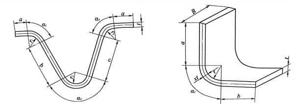
When the bending angle of the bending part is 90°, as shown in Figure 1-2, the calculation of the expansion length of the bending part can be simplified as
Lz=a+b+c+1.57(r+xt)
Fillet radius r<0.5t bending length
For the bent part with r<0.5t, because not only the rounded deformation zone of the part is seriously thinned during bending deformation, but also the adjacent straight edge part is also thinned, so the blank should be determined according to the condition of constant volume before and after deformation. length. It is usually calculated using the empirical formula listed in the table below.
| Sketch | Calculation formula | Sketch | Calculation formula |
 | Lz=l1+l2+0.4 | 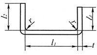 | Lz=l1+l2+l3+0.6t (Bend two corners at once) |
 | Lz=l1+l2+0.4 |  | Lz=l1+l2+l3+t (Bend two corners at once) Lz=l1+2l2+2l3+1.2t (Divided into two bends at four corners) |
Hinged bending parts by poinçonneuse
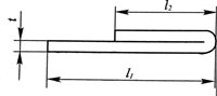
For hinge parts with r=(0.6~7.5)t, as shown in Figure 1-4, the rolling method is usually adopted to form. During the rolling process, the sheet becomes thicker and the neutral layer moves outwards. The blank length Lz can be Approximately calculated by the following formula.
Lz=l+.1.5π(r+x1t)+r≈l+5.7r+4.7x1t
In the formula, l—length of straight line;
r—the inner radius of the hinge;
X1—Displacement coefficient of neutral layer, see the table below.

| r/ t | >0.5~0.6 | >0.6~0.8 | >0.8~1 | >1~1.2 | >1.2~1.5 | >1.5~1.8 | >1.8~2 | >2~2.2 | >2.2 |
| X1(mm) | 0.76 | 0.73 | 0.7 | 0.67 | 0.64 | 0.61 | 0.58 | 0.54 | 0.5 |
Bending force calculation
Bending force is one of the important basis for selecting presses and designing molds. The magnitude of the bending force is not only related to the blank size, material mechanical properties, the distance between the fulcrums of the die, the bending radius, and the gap between the convex and concave die, but also has a great relationship with the bending method. It is difficult to accurately calculate with the theoretical analysis method. Therefore, empirical formulas are often used in production.
Free perforation and bending force
Free bending can be divided into V-shaped free bending and U-shaped free bending according to the shape of the bending part. For V-shaped parts, the formula for calculating the bending force Fz is
Fz=0.6 Kbt2??b/ (r+t)
For U-shaped parts, the formula for calculating the bending force Fz is
Fz=0.7 Kbt2??b/ (r+t)
Where Fz— the bending force of the material at the end of the stamping stroke, N;
b—the width of the bending part, mm;
t—the thickness of the bending part, mm;
r—Bending radius of the bending part, mm;
??b—Material strength limit, MPa;
K—Safety factor, generally K=1.3.
Correction of bending Obliger by power press
When the bending part is corrected by the pressure of the die at the end of stamping, the bending correction force F1 can be approximated by the following formula.
FJ=qA
Dans la formule, FJ— bending correction force, N;
q—Unit correction force, MPa, its value is shown in the table below;
A—The projected area of the corrected part of the workpiece, mm2.
| Matériel | Material thickness (mm) | Material thickness (mm) | Material thickness (mm) | Material thickness (mm) |
| ≤1 | >1~2 | >2~5 | >5~10 | |
| Aluminium | 15~20 | 20~30 | 30~40 | 40~50 |
| Laiton | 20~30 | 30~40 | 40~60 | 60~80 |
| 10~20 steel | 30~40 | 40~50 | 60~80 | 80~100 |
| 25~30 steel | 40~50 | 50~60 | 70~100 | 100~120 |
Ejector force or punch pressing Obliger
For a bending die with a top piece device or a pressing device, the top piece force Fré or the pressing force Fy can be approximately 30% to 80% of the free bending force.
Fré (or) Fy=(0.3~0.8) Fz
Determination of the tonnage of the press
The tonnage of the free bending press with elastic top piece device can be calculated by the following formula.
F presse = (1.1~1.2) (FZ+Fré)
The tonnage of the free bending press with elastic pressing device can be calculated by the following formula.
F presse = (1.1~1.2) (FZ+FY)
The tonnage of the correction bending press can be calculated by the following formula.
F presse ≥ (1.1~1.2) FJ
Dans la formule, F presse is called pressure, N.
Manufacturability of bent parts
The manufacturability of the bent part refers to the adaptability of the bent part to the bending process, which is the process requirement for the design of the bent product from the angle of the bending process. Bending parts with good manufacturability can not only simplify the bending process and the design of the bending die, but also improve the accuracy of the bending parts, save materials, and improve production efficiency.
Bending radius
The bending radius of the bending part should not be less than the minimum bending radius, otherwise it will be bent multiple times, increasing the number of processes; it should not be too large, because the accuracy of the bending angle and the bending radius is not easy to guarantee due to the effect of springback when it is too large.
The shape of the bent part
The shape of the bent part should be as simple as possible and symmetrical to the left and right to ensure that the blank does not slide during bending and cause offset, thereby affecting the accuracy of the bent part. Figure 1-5 (a) shows the prevention of sliding when the blank is bent, and the process hole positioning is added in the design. The rest parts of figure 1-5 (b), (c) shown in the small asymmetric bending parts using a pair of bending and then cutting process.

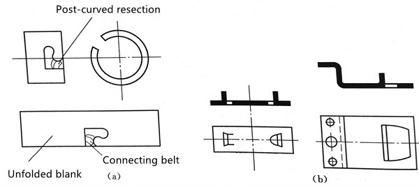
For curved parts with notches, if the notches are punched first, a fork will occur, and in severe cases, it may not even be formed. Therefore, the notch should be left as the connecting belt first, and then cut off after bending, as shown in Figure 1-6 (a).
For workpieces with incisions and bends, the bent part should generally be made into a trapezoid for easy ejection. You can also punch out the peripheral slot first, and then bend it into shape, as shown in Figure 1-6(b).
Straight edge height of bending part by presse de puissance
When bending at right angles, the height of the straight side of the bending piece should not be too small. If the straight edge height of the bent part is too small, the length supported by the straight edge on the mold is too short, and sufficient bending moment cannot be generated during the bending process, and the straight edge of the bent part cannot be guaranteed. Therefore, the straight edge of the bent part must be made straight. The edge height h>r+2t, as shown in Figure 1-7 (a). If h<r+2t, you need to slot and then bend or increase the height of the straight edge first, and then cut off the excess part after bending, as shown in Figure 1-7 (b). When the bent side has a beveled bending part, it is impossible to bend to the required angle in the area where the bevel height is less than r+2t, and the place is also easy to crack, as shown in Figure 1-7 (c) , So it is necessary to change the shape of the workpiece and increase the height of the straight edge, as shown in Figure 1-7 (d).

Bending part hole margin
When bending a workpiece with holes, if the hole is located near the bending area, the shape of the hole will be deformed after bending. In order to avoid this defect, the hole must be outside the deformation zone, as shown in Figure 1-8 (a). The distance l from the edge of the hole to the center of the bending radius r is: when t<2mm, l≥t; when t≥2mm, l≥2t.
If the distance from the edge of the hole to the center of the bending radius r is too small to meet the above conditions, the hole needs to be bent and formed before punching.
If the structure of the workpiece allows, the process hole can be punched out in advance at the bend, as shown in Figure 1-8 (b), or a process slot is reserved, as shown in Figure 1-8 (c), which is absorbed by the process hole or groove Bending deformation stress prevents the hole from deforming when it is bent.
Workpiece structure to avoid cracks at the bent root
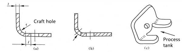
When a certain segment of the edge is locally bent, in order to avoid tearing of the bent root, the length of the unbent part should be reduced to exit the bending line, that is, b≥r, as shown in Figure 1-9(a). If the length of the workpiece cannot be reduced, a groove should be cut between the bent part and the unbent part, as shown in Figure 1-9 (b), or the process hole should be punched out before bending, as shown in Figure 1-9 (c) Shown.

Increase process gaps, grooves and process holes
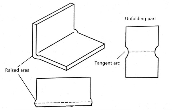
For bent parts with distortion on the side of the rounded deformation zone during bending, in order to improve the dimensional accuracy of the bent parts, process notches or grooves can be cut at both ends of the bending line in advance to avoid the influence of distortion on the width of the bent parts, such as As shown in Figure 1-10.
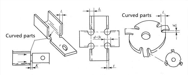
When the edge of the workpiece needs to be bent locally, in order to prevent deformation and cracks caused by uneven force on the bent corners, grooving or punching holes should be pre-cut, as shown in Figure 1-11. Among them, the process groove depth L≥r+t+K/2, the process groove width K≥t, and the process hole diameter d≥t.
Accuracy of bending parts by poinçonneuse
The accuracy of the bending part mainly refers to the accuracy and stability of its shape and size. The accuracy of the bent part is affected by factors such as the mechanical properties of the sheet material, thickness, mold structure, mold accuracy, number of procedures, sequence of procedures and the shape and size of the workpiece itself. Generally speaking, the economic tolerance level of bending parts is below IT13 level.

Learned a lot here!
I understand the knowledge and principles of stamping and bending at once!